| View Couplings | |
|
Alignment Procedures
|
|
 |
 |
|
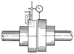
Figure 1
|
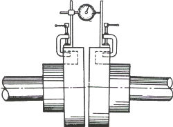
Figure 2
|
|
The preferred method of measuring coupling alignment is with Laser equipment. Dial indicating tools as shown in figure 1 and 2 are alternative methods. Clamp the dial indicator to the coupling halves as indicated above ( figure 1 , 2) and indicate the position of the dial button on the opposite coupling half with a chalk mark. Set the indicator dial to zero at the first position and then rotate both halves of the coupling to a new position where a check reading is to be made. All readings must be made with the dial button located at the chalk mark, and not less than six different sets of readings should be taken. A variation in the dial reading at different positions of coupling rotation will indicate whether the machine has to be raised, lowered, or moved to one side or another to obtain alignment of the circular concentric peripheral surfaces of the two coupling halves within the specified tolerance. Clamping a reference surface to the opposite coupling half allows the dial indicator to be used for measuring the the separation of the coupling halves for axial alignment as shown figure 2. |
|
 |
 |
|
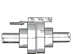
Figure 3
|
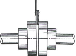
Figure 4
|
|
The straight edge or thickness gauge or feeler gauge is an alternative method of measuring coupling adjustment as shown in figure 3 and 4. Use a straight edge and thickness gauge or feeler gauge to check the alignment of the circular concentric peripheral surfaces of the coupling halves as shown above. The separation between the faces of the coupling halves can be measured as shown. |
|